Water Meters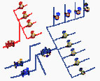 The system diagram below shows several applications for some of the more popular products from the Timely range of water meters.
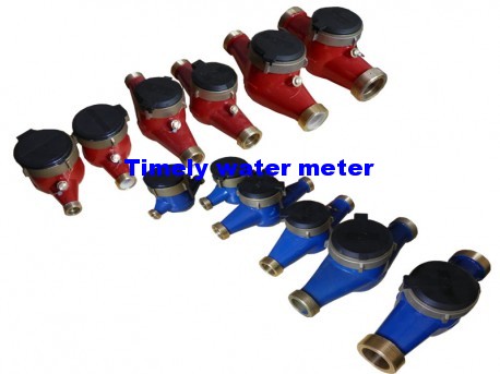
In water meters for both hot and cold water applications are shown. On both the hot and cold water systems a bank of single-jet water meters is depicted. This sort of configuration could be used when water consumption for individual flats or offices needs ![]() to be recorded. Pulse output meters, suitable for connection to a building management system or electronic remote readout, are also available. Also shown on the hot water system is a multi jet water meter, which is a class B meter, available in standard or pulse output versions. On the cold inlet side of the system meters from the Woltman range of large industrial and irrigation water meters are shown.
to be recorded. Pulse output meters, suitable for connection to a building management system or electronic remote readout, are also available. Also shown on the hot water system is a multi jet water meter, which is a class B meter, available in standard or pulse output versions. On the cold inlet side of the system meters from the Woltman range of large industrial and irrigation water meters are shown.
Diagram 1
Definitions
Nominal Flow Rate | Qn | The designation flow rate of the meter. |
Maximum Flow Rate | Qmax | The highest flow rate at which the meter accuracy will be within the maximum permitted error. |
Minimum Flow Rate | Qmin | The lowest flow rate at which the meter accuracy will be within the maximum permitted error. |
Transitional Flow Rate | Qt | The flow rate at which the maximum permitted error of the meter changes. |
Maximum Permitted Error from Qmin to Qt |
| ± 5% |
Maximum Permitted Error from Qt to Qmax |
| ± 2% |
Type | Class | Nominal Flow in m3/h | Dry Dial | Wet Dial | Liquid Sealed | Cold Water | Hot Water | Pulse Version | Vertical | Horizontal |
Single jet meters | A&B | From Qn 1.5 to Qn 10 | x | x | x | x | x | x | x | x |
Multi jet meters | B&C | From Qn 1.5 to Qn 15 | x | x | x | x | x | x | x | x |
Volumetric rotary piston meters | C | From Qn 1.0 to Qn 2.5 | x | a | x | x | a | x | x | x |
Woltman industrial meters | A&B | From Qn 15 to Qn 1500 | x | x | x | x | a | x |
| x |
Installation Instructions
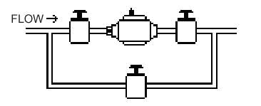 Diagram 2
4. Do not overtighten connections; tighten only as required to seal. Do not use pipe sealant or Teflon tape on meter threads.
5. If meter is equipped with an electrical contacting head register, line up molded tabs on inside of reed switch with corresponding indentions of receptacle on face of meter. Insert reed switch and turn 1/4 turn to lock in place.
6. Tie black and red wires on opposite end of reed switch to corresponding black and red water meter wires on controller. Insulate connection with water-proof wrapping.
7. With upstream shutoff valve only:
Open shutoff valve slowly, to remove air from the meter and service line. Open a faucet slowly to allow entrapped air to escape. Close the faucet.
With both upstream and downstream shutoff valves installed:
To test the installation for leaks: Close the outlet (downstream) shutoff valve. Open the inlet (upstream) shutoff slowly until meter is full of water.
Open the outlet (downstream) valve slowly until air is out of meter and service line. Open a faucet slowly to allow entrapped air to escape. Close the faucet.
Unit F101, Xinwei Ind. Zone, Guangming Dis., Shenzhen, 518106, China
Email: timely@timelycn.com
Website: http://www.timelycn.com/
Copyright@2014 TIMELY, All rights reserved. http://beian.miit.gov.cn/
 Home
Home